MCU
MCU Setup
The multicore processor in this project is used to keep track of the current brush state, the color state, the thickness of the brush, and whether the brush is up or down. The system collects this data and then sends it to the FPGA board for VGA processing via a SPI packet. There are two primary SPI packets used to communicate the status of bits, and they are organized such that the header of the color SPI block is easily distinguished and decoded.
Schematic
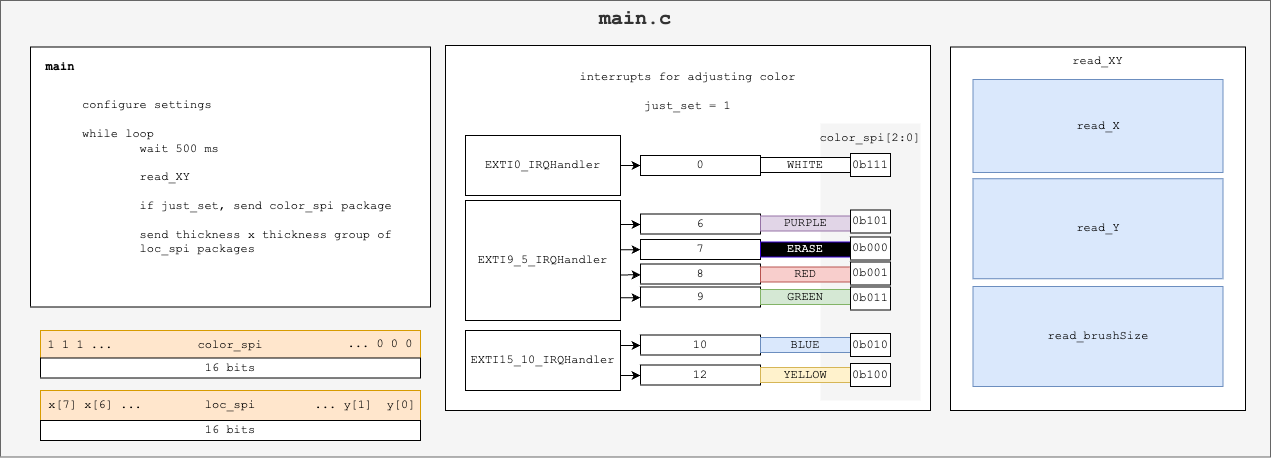
The MCU makes use of many of the materials and ideas seen throughout the semester in MicroP’s. It uses interrupts in order to assign the brush’s current color, with a total of seven potential colors (including erase).
The system also implements the newer technology of analog to digital conversion (ADC) on the MCU, which is used to determine the current state of a joystick for location control, as well as a potentiometer to control the thickness of the brush at any given time (ranging from 1x1 to 2x2 to 3x3).
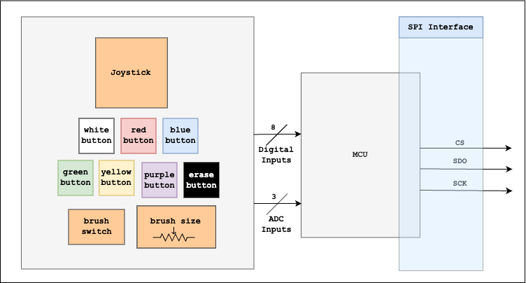
When compiled together, this gives Figure 1. The detailed layout of the pins can be found in the dropdown containing Figure 2.
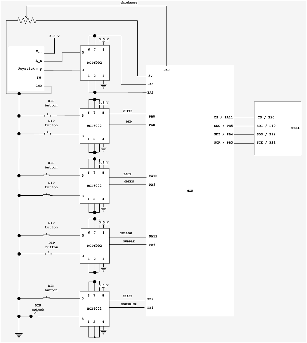
Each of the buttons and the analog control of the joystick has an op-amp attached to it. This was done while breadboarding, as significant loading was noted specifically on the part of the joystick. The op-amps were added to the buttons as an extreme precautionary measure, although this was likely unnecessary.
The program starts first by initializing all of its components before entering a while loop, which controls the main functions required of the MCU. This while loop delays for some 500 ms, before calling read_XY to find the current state of the joystick and to update the size of the brush. This information is used to determine what SPI packets are sent at the end of the while loop. In the case that an interrupt has occurred or the switch controlling whether or not the brush has been raised or lowered has changed, color_spi is updated.
The behavior of interrupts is depicted in Figure 3.
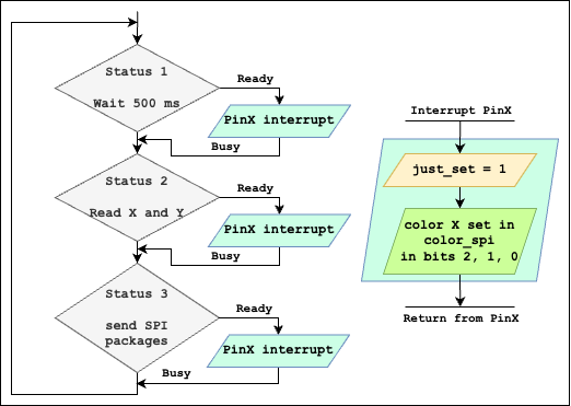
just_set and adjust the color of the SPI.
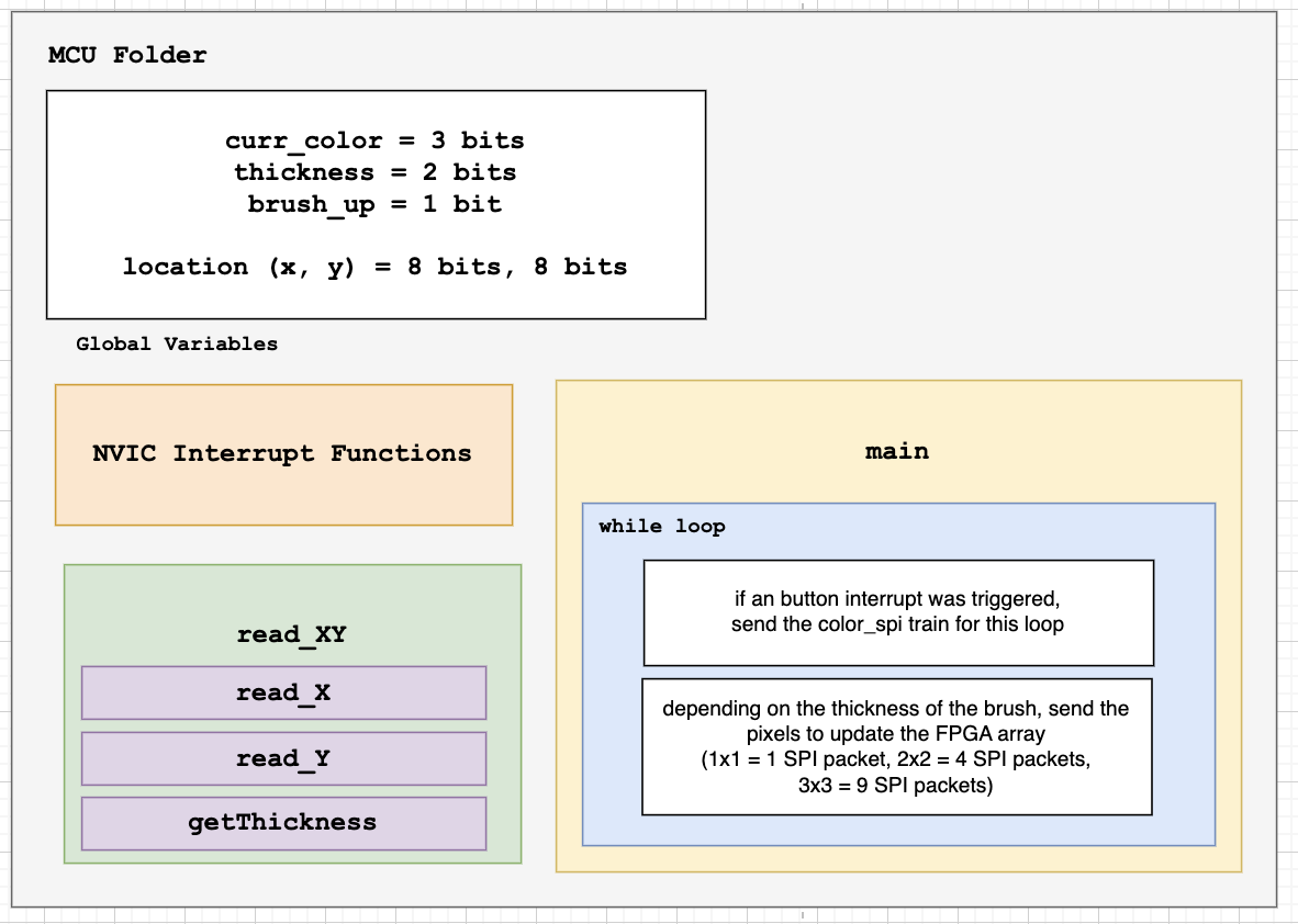
The block diagram below (Figure 4) depicts the general variables and assignments used within the MCU program. An even more generalized view can be found in Figure 5.
SPI
The program is able to send out all the locations necessary dependent on the current thickness of the brush. This can be seen in the set of images below:
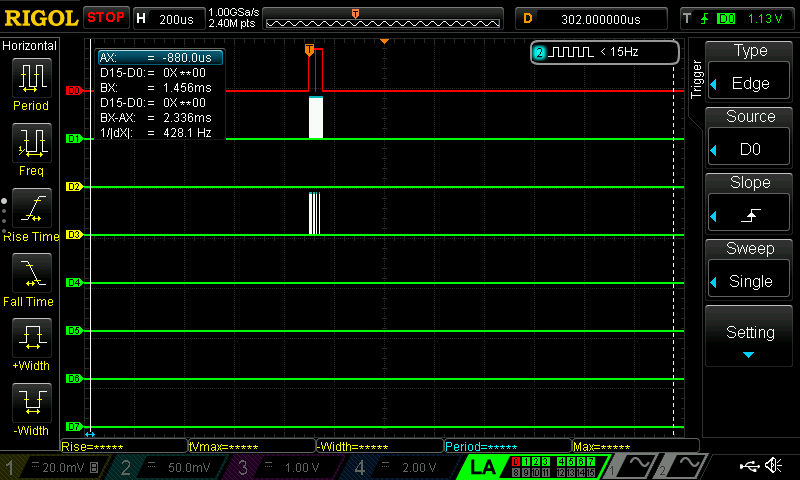
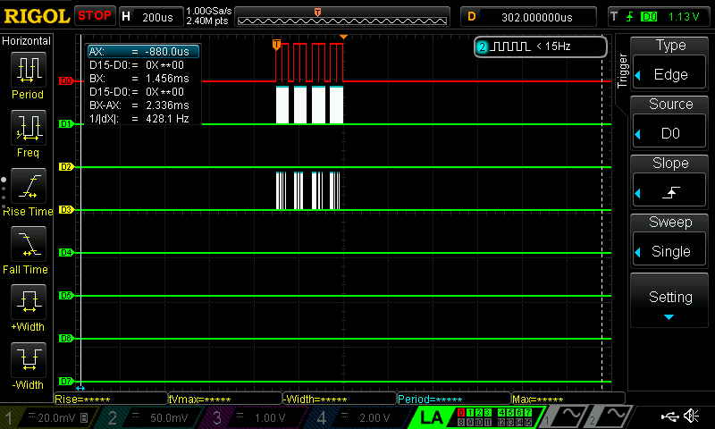
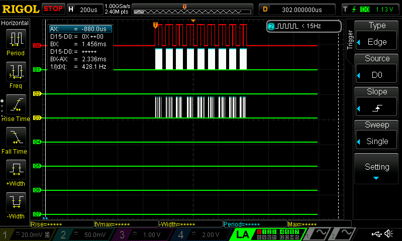
The files are sent in this way to ensure the simplest possibe implementation on the FPGA. The FPGA board currently uses combinational logic to interpret the incoming SPI data, and as a result, by sending each pixel that should be currently turned on, the MCU prevents the FPGA from needing to use a finite state machine in order to interpret the data it is placing in the RAM at any given time.
In addition, when a button is pressed, the color_spi spi packet is sent along with the location data, which contains information on whether the brush is down or up, as well as what color the current SPI bus is.
The maximum possible number of SPI packets sent in a given round is 10 (each SPI packet is considered to be to collections of 8 bits), and the minimum is 1.
A “SPI Packet”, as we have deemed, can be of two types:
color_spi

loc_spi

These SPI packets are differentiated by the first three bits of the SPI message: in the case of color_spi, the first three bits will always make the value of the byte greater than 200, which is impossible for the x and y indices to be. As a result, the SPI packets can be easily differentiated with the use of the first three bits, which the FPGA will figure out combinationally and will then use to adjust its values accordingly.
The video below is a demonstration of the data being sent out of the MCU at any given time.